Safety Instrumented Systems
Most of the world’s 600 or so ammonia plants and their associated downstream derivatives facilities were built in the last century. Although technologically advanced when built, they are not as safe as today’s new plants, which typically use programmable logic controllers (PLCs) with triple modular redundancy (TMR).
Before the 1970s, process safety relied to a large extent on pneumatic trips. PLCs did not penetrate the market until the 1980s. TMR arrived in the mid-to-late 1990s along with smart digital transmitters. PLCs with Safety Integrity Level 3 (SIL 3) are now standard. Currently, continuous transmitters are displacing switches because operators can more easily change their settings and because smart transmitters have far fewer dangerous, undetected failures than switches. However, systemic failures can still occur in revamps because operators tend to replace existing systems without checking the effect of a revamp on the entire plant.
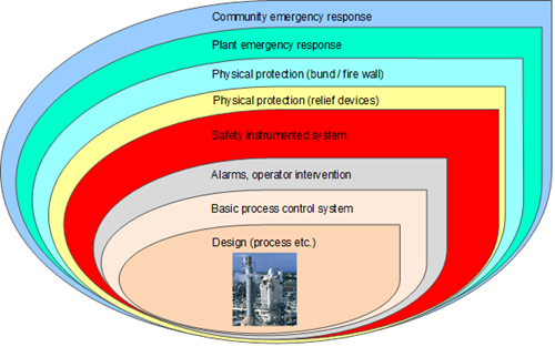
Figure I
Plant design is at the core of plant safety. The Basic Process Control System (BPCS) comes next, followed by operator intervention, alarm systems, and the Safety Instrumented System (SIS). The SIS is an important layer of protection because it can provide the highest level of protection when compared with other layers shown in Figure I.
Figure II identifies the safety-related monitoring steps over a plant’s life cycle. Safety oversight continues until a plant is decommissioned.
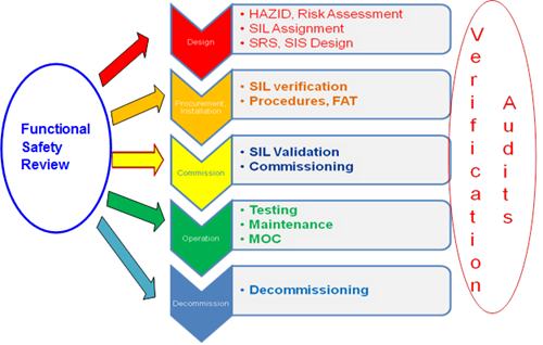
Figure II
The design of a plant’s SIS begins with Hazard Identification (HAZID) and risk assessment, once the Process and Instrumentation Diagram (P&ID) is ready. Nowadays, most companies mandate risk assessment whether the project is an upgrade or a brand new plant. The project’s Safety Instrumented Functions (SIF) are then identified and SILs assigned. Each SIL (1 through 4) represents an order of magnitude of risk. The higher the SIL, the greater the expected impact of a failure is. Table 1 shows the relationship between SIL and the probability of failure.
| SIL Rating | Low Demand Application | High Demand / Continuous Application |
| Average probability of failure to perform design function on demand – PFD | Probability of dangerous failure per hour | |
| 1 | 10-2 to 10-1 | 10-6 to 10-5 |
| 2 | 10-3 to 10-2 | 10-7 to 10-6 |
| 3 | 10-4 to 10-3 | 10-8 to 10-7 |
| 4 | 10-5 to 10-4 | 10-9 to 10-8 |
Table 1
The SIL allocation techniques, shown in IEC 61511, are:
- Risk Matrix
- Risk Graph
- Layer of Protection Analysis (LOPA)
- Quantitative Assessment (detailed calculation using techniques such as Fault Tree / Markov analysis)
The first two techniques are qualitative. The risk matrix is generally used for screening. The risk graph was commonly used until few years ago. It is shown in Figure III.
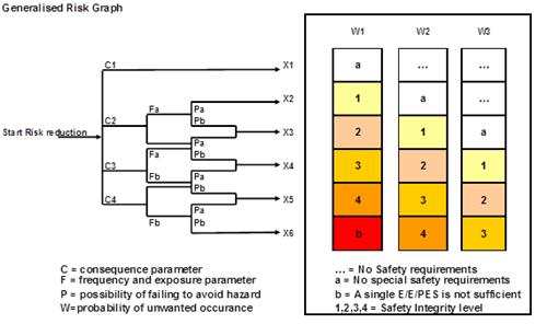
Figure III
Risk graph analysis usually takes a team of process engineers, instrument engineers, and operating personnel. Since qualitative analysis is subjective, LOPA, a semi-quantitative method, is currently the preferred way to determine SIL. Table 2 is a typical LOPA template. LOPA software is commercially available.
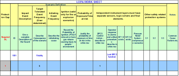
Table 2
In the LOPA method, the plant owner sets the target tolerability criteria. The standard criteria for preventing a fatality is one in a million per year. The SIL requirement is the net difference between the target tolerability and the sum of failure frequencies mitigated by various independent layers of protection already built into the plant design.
A major accident can have multiple initiating causes, each with its own frequency of occurrence. For example, over-pressuring a vessel can rupture the vessel, which, in turn, might cause a fire, an explosion, and/or a toxic release. Initiating causes such as a loss of cooling water supply, a temperature control loop failure, or a blocked outlet might trigger the incident. Each of these initiating causes can have a different frequency of occurrence and different risks (consequence x frequency). A SIF requirement is derived for each initiating cause and, normally, the highest SIL of all the scenarios is used. Cases that have a large number of causes or multiple scenarios with the same or similar SIL (risk) may warrant a look at the overall SIL because it could be higher than the individual SILs.
Over-rating the SIS system may increase Capex and Opex and under-rating may not protect the plant fully from major accidents. A study of several ammonia plants’ SIS indicated a significant SIL-spread between the risk graph and LOPA methods. Therefore, a review of the SIL allocation study by a peer group and/or independent specialist is recommended, especially when SIL 3 or higher ratings are involved.
For a typical ammonia plant, the following items are rated SIL 1 and 2:
- Steam reformer fuel-gas flow, pressure
- Steam reformer firebox pressure
- FD fan discharge pressure
- Reformer flue gas temperature high and low steam flow (during start-up)
- Reformer outlet process gas temperature
- Reformer steam flow
- Steam reformer low steam-to-gas ratio
- Steam drum level low (or flow)
- Secondary reformer air-to-gas ratio
- Secondary reformer temperature
- CO2 solvent flow
- CO2 absorber level
- Methanator catalyst bed temperature high
- Synthesis gas compressor KO drum level
- Synthesis gas compressor auxiliary (lube, seal oil where applicable) functions
- Ammonia compressor KO drum high level
- Flare pilots
- Ammonia storage tank level, temperature, foundation heater, recirculation compressor suction pressure
- Start-up heater burner management, etc.
SIS systems related to package units such as the syngas, air and refrigeration compressors, and drivers can also be combined with the process unit’s SIS.
About 70 percent of SIFs for ammonia/urea plants are rated SIL1 or lower. About 30 percent are SIL 2. Occasionally, a plant is rated SIL 3, but generally SIL3 is avoided because of its higher cost.
The SIL allocation step provides the list of SIL-rated systems and determines the SIS logic solver’s size. A Safety Requirement System (SRS) and functional design specification is developed for procuring the components.
Many plants have chosen to upgrade safety instrumentation on a piecemeal, maintenance-replacement basis. For example, they have upgraded a PLC to SIL 3 without modifying the associated transmitters and shutdown valves, even though these field devices contribute significantly to failure rates. Experience shows that budgeting liberally from the beginning of a safety upgrade project saves costly retrofits later.